Active Suspension System
For my senior capstone project, my group chose to design an offroad trailer system. Since this was during COVID, we only had to design our project and not assemble any hardware — so my group decided to tackle a relatively large project. Our team consisted of 4 mechanical engineers (3 of whom focused on mechanical design, and I focused on controls), and 3 electrical engineers (who focused on the sensor implementation and power systems).
Problem Statement
In a search-and-rescue scenario in intensely offroad environments, patients must be transported and possibly operated upon over difficult terrain. Helicopter airlifts are often prohibitively expensive, both in operational costs and costs to the user (in the US around $10k and $40k respectively). However typical offroad suspension systems are inadequate for intensely rough terrain in mountainous or rocky environments.
Our Solution
Our solution to this problem was a trailer which would be capable of being towed over very rough terrain by any common truck or Jeep. Additionally, since the injured patient could be in a critical condition, a bumpy ride could make injuries worse. For this reason we determined that the trailer must have some kind of active suspension system to minimize the acceleration felt by the passengers inside.
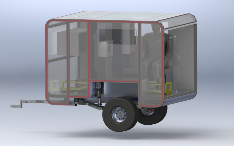
The render above shows the general setup of the vehicle. It has enough internal volume for one injured patient on a gurney and one seated EMT next to the patient, as well as medical equipment. Under the floor are batteries which power the main actuators as well as the sensors and any medical systems inside.
The Actuation System
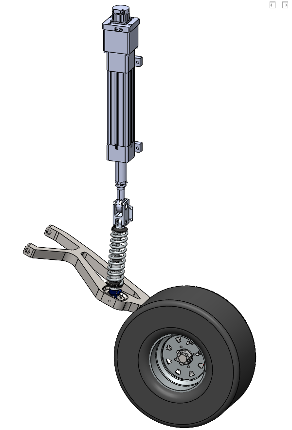
We iterated through a number of active suspension design configurations. Ultimately what we chose was one linear actuator controlling each independent suspension assembly. This linear actuator is placed in series with an off-the-shelf passive shock absorber. We determined that this was the best configuration for our need, given that this big actuator had a relatively small bandwidth.
We figured out how to package the actuator nicely within the envelope of the vehicle without encroaching on usable interior space.
The Sensing System
We implemented a number of sensors on the vehicle, including two hall-effect wheel speed sensors, an accelerometer, a gyroscope, two rotary encoders, and two LiDAR sensors. The first four are used to estimate the state of the vehicle with a Kalman Filter (more on that below), and the LiDAR sensors are used to generate terrain maps of the ground ahead of the vehicle.
The LiDAR sensors output point clouds of the terrain in front of the vehicle, and using computer vision algorithms we were able to pretty efficiently create a relatively accurate terrain surface. This terrain map is used by the control system (read below) to respond to incoming disturbances with the actuator before they even reach the vehicle.
My Contribution: The Control System & General Architecture
So we have actuators and sensors. But what do we do with them?
This is what most of my work went into for this project. The very cool part about this LiDAR architecture (and, to be fair, the reason we included it in the first place), was to gain access to future disturbance data. Depending on the speed the vehicle was traveling, we had anywhere between 1 and 5 seconds of estimated terrain height in front of the trailer. So the question is how do we implement this into the control system.
The solution I designed was a combination of feedforward and feedback control. The block diagram for the full control system is shown below.
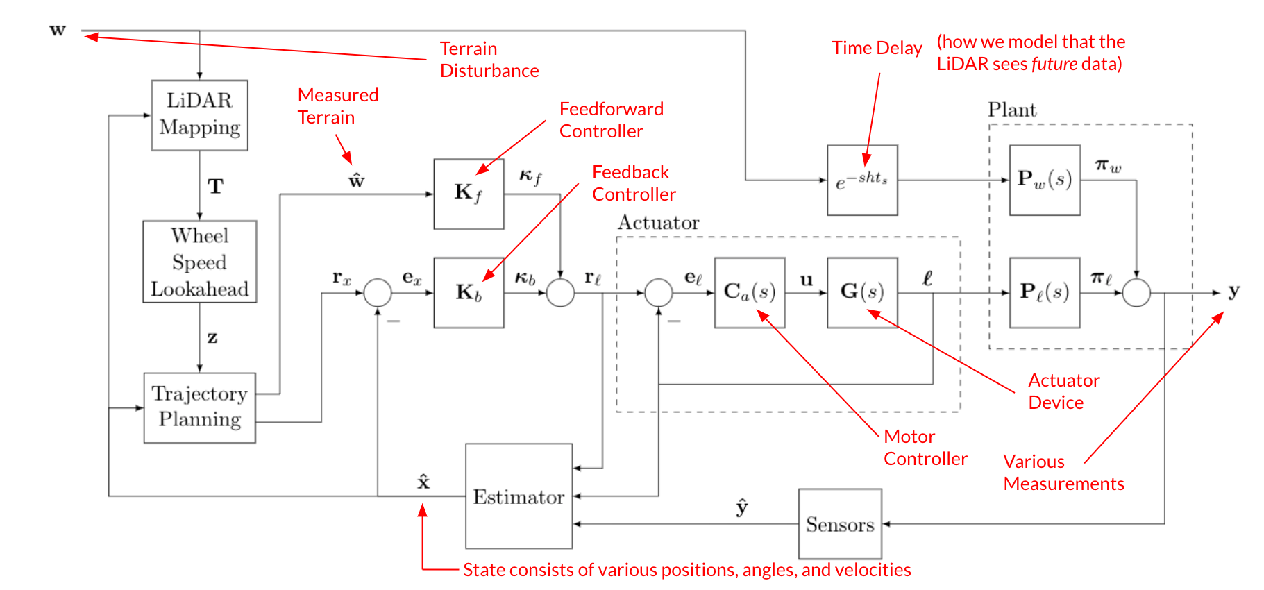
It’s a lot to take in, so let’s walk through it briefly. The terrain \(w\) is sensed by the LIDAR, and processed by the lookahead algorithm and then a trajectory in planned. This measured terrain \(\hat{w}\) is passed into the feedfoward controller \(K_f\) which commands a reference position to the actuator system. The off-the-shelf actuator we selected has its own position-control feedback loop which is modeled here, but the important part is that given a reference length \(r_\ell\) the actuator will move to position \(\ell\) via some known closed-loop transfer function. This actuator length influences the vehicle state, which we model as the length-to-output plant transfer function \(P_\ell\).
Additionally, this terrain disturbance will hit the disturbance-to-output vehicle plant \(P_w\), however we modeled a pure delay before that happens. This is our way of encoding that the terrain seen by the LiDAR \(w\) is in the future, and will take some amount of time (\(ht_s\)) to affect the vehicle.
Then as with any full-state feedback control system, we take various state measurements (with position sensors, gyroscopes, accelerometers) which are passed into a Kalman Filter. Then our estimated state \(\hat{x}\) is compared to the reference state \(r_x\) (which usually consists of all zeros) and that error is fed into the feedback controller \(K_b\).
The feedforward controller is designed to minimize the effect that \(w\) has on \(y\). Specifically, we want to minimize \(\|\pi_w - \pi_\ell\|_\infty\). The most straightforward way to do this for this application is to invert the plant as well as possible in the ranges we care about. No time to dive into the nitty gritty, but in the end I designed a feedforward controller which yielded good results.
The estimator and feedback controller were very simple to implement. For the estimator, we had modeled noise in each of our sensors, and we also had researched models describing typical terrain disturbance profiles. So it was quite trivial to form the required measurement noise and process noise covariance matrices and let MATLAB calculate the Kalman Filter gains from that. This yielded satisfactory results. And for the feedback controller we used LQR, because it’s in many ways the most easy MIMO controller to implement. the \(Q\) and \(R\) matrices were tuned by hand, and in the end the results achieved what we wanted.
Control System Results
The overarching goal of the whole control system, was to minimize the acceleration that the patient experiences, in the 1-4 Hz band. This was incluenced by a number of physiological and automotive studies in addition to military vibration standards.
First we will loook at the disturbance step response of the vehicle (that is — the vertical position of the vehicle when encountering a positional step, i.e. rolling over a rock or ledge). Recall, we want to minimize the acceleration of the patient, so minimizing any fast positional changes is what we’re looking for. Also recall from above, our goal is to make \(\pi_\ell \approx -\pi_w\), so that the actuator “cancels” out the disturbance.
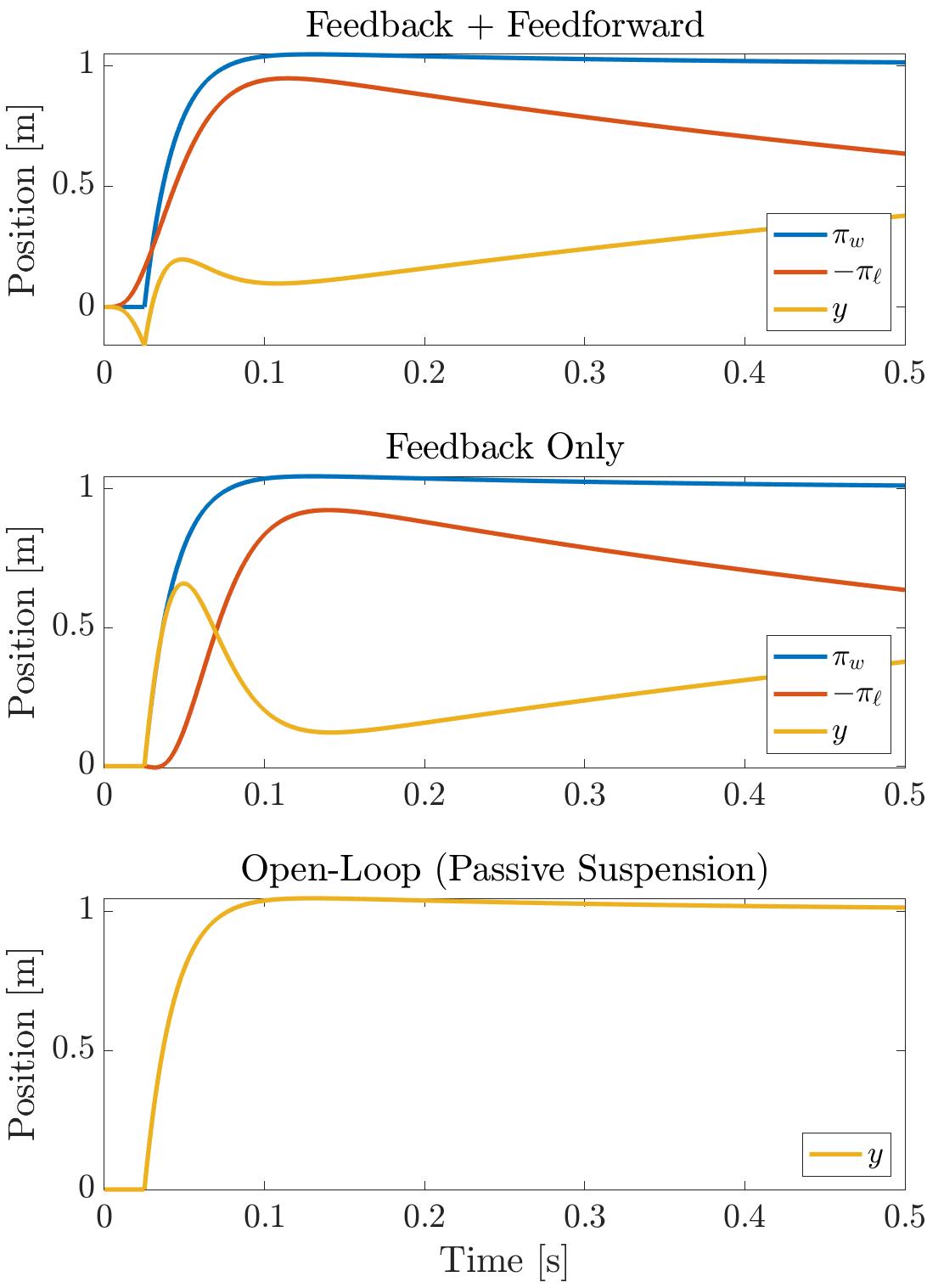
The top plot shows that the actuator starts to respond before the step hits (which is the whole point of the LiDAR). When it does this it is able to cancel out the disturbance much better. Note that the actuator, like any physical system, is band-limited, so the feedforward controller in a sense times when to start moving the actuator while predicting when the disturbance will hit. In contrast, the second plot shows what happens when the control system is purely reactive, so the actuator can only start responding after the step has hit.
We can view these similar results on an acceleration PSD, shown below.
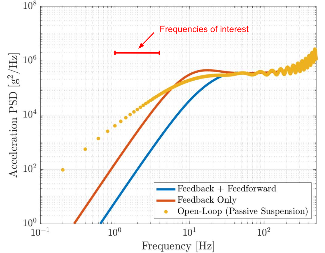
This webpage is already too long, but basically this plot shows that the patient experiences significantly less acceleration with the feedback + feedforward system, compared to the purely feedback or the fully open-loop systems. Further analysis showed that the feedback + feedforward system yields acceleration magnitudes below the ISO 2631 exposure limit, while the only feedback and open-loop configurations were above the limit. Therefore the control system design was successful.